Business Articles - Specialty and Trade
Articles & Tips
Laying out rake walls is easy with a calculator and a few simple keystrokes
by Eric Dickerson
Rake walls are common in house design, but building them is far from routine. Unless you have developed a standard method for framing these walls, the first time you encounter a complex design combining vaulted spaces with intersecting dormers, you’ll spend a lot of time scratching your head. This article describes the techniques I’ve developed after years of experience framing rake walls.
From the Top Down
When I’m getting ready to frame a complex house, I do my figuring
from the roof down instead of from the sill plates up. Most framers look first
at the foundation plan, then the floor plans, and so on; I look first at the
roof. In a complicated house, it’s easy for the designer to get lost in
the elevations. Because I’ve seen my share of roof plans with eaves that
pass through windows and hip beams that cut through doorways, I make sure all
of the roof planes come together properly before I start calculating wall
heights. Once I can visualize how the roof creates the spaces below, I can
figure out how to frame the walls that support the roof. I rarely use the
elevations provided on the plans without double-checking. The roof design
determines the wall elevations; unless the roof changes, the wall heights
can’t change.
It’s also important when framing rake and other tall walls to work in the proper sequence. You want to avoid leaving a tall wall standing alone on the subfloor with braces all over the place. Whenever possible, frame any adjacent walls first and stand the balloon wall between them.
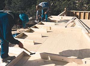
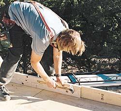
To ensure that I don’t miss any rake walls, I typically figure the elevations before I plate my subfloor. The more complicated the roof, the more you need to pay attention to how to plate your walls and the heights of those walls. I write down as much information as I can directly on the plates or on the subfloor nearby so that I don’t need to keep referring to the plans when I’m building the wall (see Figure 1).
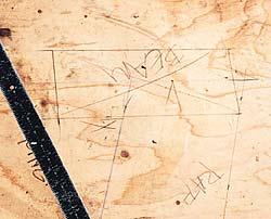
Figure 1. While laying out rake walls, the author draws details at full scale on the subfloor. To avoid having to continually refer to the plans while framing, he also writes dimensions for plates, studs, jacks, trimmers, and headers directly on the deck.
I write down the lengths of the longest and shortest studs and the length of the top plate from short to long point, plus the length of trimmers and cripples, window rough openings, and header lengths. With an inexperienced crew, I may even cut the top plate, king studs, and headers, and position them on the subfloor near the layout marks.
In some cases, I also write down the kind of lumber that should be used. It’s difficult to find 2-by material these days that is both long and straight, so I often use laminated veneer lumber (LVL). Also, because LVL studs are stronger and stiffer than sawn lumber, they are often specced by engineers for tall walls. With sawn studs, engineers sometimes spec doubled studs to add strength to the wall.
I usually block balloon walls every 8 feet to strengthen the diaphragm. I install the blocking on edge so that it also serves as fire blocking.
When it comes time to lay out a rake wall, I first snap out the perimeter of the wall at full scale on the subfloor (Figure 2).
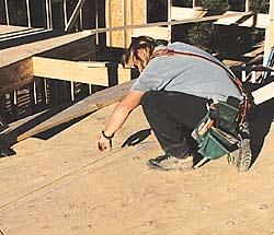 |
Figure 2. The perimeter of a rake wall is snapped out on the subfloor, along with lines for all studs, and headers and sills for window and door openings. |
I also snap out the king and common studs, as well as the headers and sills of all window and door openings. If there are any beam pockets in the wall, I lay out their elevations on the subfloor as well. For instance, if I have a large ridge beam that needs to sit in a pocket in the rake wall, I draw a full-scale mockup of how the rafters connect to the ridge beam so that I know the exact elevations of the beam and post in the rake wall.
Rake Wall Math
I use a calculator to figure the elevations, and I double-check my layout as I
go. Because my calculator falls out of my pouch a lot, I don’t use an
expensive feet-and-inch model; instead, I have a Texas Instruments scientific
calculator. It has all of the trigonometry functions I need, plus three
memories (which is three times what I have). Once you learn how to convert
decimals to feet and inches on a regular calculator, it’s easy to do all
the job-site math.
Rake wall height. To figure the high point of a rake wall where it intersects the ridge, I first measure the deck and convert feet and inches to decimals. (The building footprint has a way of growing or shrinking a little, so I prefer to use actual measurements rather than reading the dimensions off the plans.)
For example, if the house is 26 feet 6-3/4 inches wide, the span (the measurement to the center of the ridge) is 13 feet 3-3/8 inches. Convert the inches to decimals (see ), and plug the results into the formula. In this example, the center of the ridge is at 13.28 feet which, when multiplied by the roof pitch, gives you the rise in feet of the highest point of the rake wall. For a 6/12 pitch, the formula is:
6/12 = .5
.5 x 13.28 = 6.64
Add this to the height of the wall at the eaves and you’ve got the elevation of the rake at its highest point. If the eaves are at 8 feet, the total height is 14.64 feet (8 + 6.64).
Whether or not you add the length of the rafter plumb cut to this dimension depends on how you treat the rake wall at the roof line. I usually cantilever lookouts over the rake wall, tying them into the rafters one or two layouts back. For a shallow overhang (less than 18 inches), I use 2x6s on the flat, so I typically frame the rake wall 11/2 inches shorter (measured square to the rafter) than the elevation of the rafter tops. For lookouts on deeper overhangs, I use 2x6s on edge, so I frame the rake 51/2 inches lower than the top of the rafters.
With some truss roofs, such as scissor trusses, I have seen framers build rake walls to the underside of the truss. But this creates a place where the wall can buckle, and you also have to remember to order a shallower gable truss so you can shoot the lookouts over the top without notching. With trusses, I prefer to omit the gable truss and frame the rake wall to the underside of the lookouts.
Length of top plate. To figure the length of the top plate from short to long point, I typically use the following keystrokes on the calculator, in this order: pitch ÷ 12, inverse tangent, cosine, 1/x. For instance, with a 6/12 roof pitch, the unit length (the length of the sloping plate per foot of horizontal run) of the top plate is:
 |
6/12 = 0.5 |
To find the plate length in decimals, first round off 1.118 to 1.12, then multiply by the span: 1.12 x 13.28 = 14.87 feet. Now convert to feet and inches. The article "Stacking Supported Valleys" (9/97), by Will Holladay, concerning methods for figuring rafter lengths, is helpful for rake wall top plates as well. Mr. Holladay does a great job of taking the mystery out of the math.
Framing the WallThe first step in actually framing the wall is to cut the sole plate and
toe-nail it on edge to the subfloor (Figure 3).
 |
 |
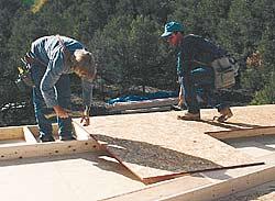 |
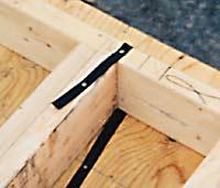
Figure 3. Framing begins by toe-nailing the sole plate to the deck (top left). Before sheathing the wall (left), fasten steel binding straps around the plate (top right) and nail them to the joists. This will keep the wall from kicking out when you stand it up. |
This allows me to frame the wall right over my snapped layout lines. Since I’ve already done all the math while snapping the layout, I physically lay studs on the deck and scribe the bevel cut where the stud crosses the top plate. I start with the longest and shortest studs; if there are a lot of windows, I frame all the king studs next.
Before standing a tall wall, I use a metal lumber strap to anchor the sole plate to the deck in a few places. These straps keep a tall wall from kicking out at the bottom as we lift it. Facing the edge of the deck, I slide a strap under the sole plate, then bend it up and nail through the strap into the edge of the plate. I use a 16d nail fully set. I nail the rest of the strap through the subfloor into solid floor framing in three or four places.
On most walls, I install all of the sheathing while the wall is still on the deck. If the wall isn’t too large and heavy, I raise the wall up high enough to slide some sawhorses underneath. Then I nail a couple of long 2x4s or 2x6s to the side of a post or king stud within the wall. (I avoid the studs at either end, because the push-sticks will get in the way later and have to be removed.) I nail the 2-bys with a couple of 16d nails, placed close together so that as we raise the wall, the push-sticks will rotate. The push-sticks add overhead leverage and balance, and serve as braces after the wall is standing.
I never use this method, however, on an extra-tall or very heavy balloon wall. It’s just too difficult and dangerous to raise a wall when most of the weight is way above your head as you raise it. For some large walls, I use Proctor wall jacks (Proctor Products, P.O. Box 697, Kirkland, WA 98083; 425/822-9296), which are slow but safe, and give me complete control over the lift. If I have a lot of tall, heavy walls, I use a crane. In this case, I try to schedule the crane for a time when it can also be used to lift beams and trusses into place.
Once the wall is standing, I plumb and brace the center of the wall and throw a few more braces on king studs or posts. I also nail diagonal braces to adjacent walls from top plate to top plate to add some strength to the wall until it’s completely plumbed and lined. In Colorado, where I live and work, it gets really windy, and it sometimes seems that I use more braces than studs. But those tall rake walls are like sails and I wouldn’t want to lose one.
Feet-inch calculators make it easy to work with building dimensions, but you can convert between decimals and feet-inches using an ordinary calculator. The easiest way to explain the steps involved is to work through the sample dimensions I mention in the main article.
Converting feet-inches to decimals. The span in my example is 13 feet 3-3/8 inches. To convert this to a decimal, first solve the fraction; next, add the number of full inches, then divide by 12; finally, add the full number of feet. Enter the numbers or operations into the calculator in sequence, one after the other:
![]()
3 ÷ 8 = .375 + 3 = 3.375 ÷ 12 = .28 + 13 = 13.28.
In decimals, then, the center of the ridge is at 13.28 feet.
Converting decimals to feet-inches. The key to working in the other direction — decimals to feet-inches — is to remember that you’re always working with either 12ths of a foot or 16ths of an inch. Let’s work the problem in the article, which is to convert 14.87 feet to a feet-inch measurement. What we’ll do is subtract out the feet and multiply the fractional part of the decimal by 12, which gives us full inches plus a remainder; subtract out the full inches and multiply the remainder by 16 to get sixteenths of an inch (again, key in the following numbers or operations in order):
![]()
14.87 - 14 = .87 x 12 = 10.44 -10 = .44 x 16 = 7.04
Now add the whole numbers together and you get 14 feet 10 and just over 7 sixteenths inches. Simple.
Pulling diagonals. This method is also handy when you have to pull long diagonals to square up a foundation or deck. Following the Pythagorean Theorem (a² + b² = c²), take feet-inch measurements of the two sides, then use the calculator to convert them to decimals and find the square. Add the squares together, then take the square root. Convert this decimal number back into feet-inches and check it against your measurement of the diagonal.
For example, say a foundation is 21 feet 8-7/8 inches on one leg, and 15 feet 9-1/4 inches on the other. The calculations to find the feet-inch dimension of the diagonal should go like this:
Long leg (a²):
work the fraction 7 ÷ 8 = .875
add full inches 8 + .875 = 8.875
divide by 12 8.875 ÷ 12 = .7395
round up and add feet 21 + .74 = 21.74
find the square 21.74 x 21.74 = 472.6276
Short leg (b²):
1 ÷ 4 = .25 + 9 = 9.25 ÷ 12 = .771 + 15 = 15.771
15.771 x 15.771 = 248.7244
Diagonal (a² + b² = c²):
472.6276 + 248.7244 = 721.352
The square root of 721.352 = 26.858
Convert to feet-inches:
26.858 - 26 = .858 x 12 = 10.296 - 10 = .296 x 16 = 4.736
The diagonal should be 26 feet 10 and just under 5 sixteenths inches long.
Close enough.
Eric Dickerson, a long-time framing sub, owns and operates a general contracting company in Ridgway, Colo.
This article has been provided by www.jlconline.com. JLC-Online is produced by the editors and publishers of The Journal of Light Construction, a monthly magazine serving residential and light-commercial builders, remodelers, designers, and other trade professionals.
Join our Network
Connect with customers looking to do your most profitable projects in the areas you like to work.